

close
Choose Your Site
Global
Social Media
Views: 0 Author: Site Editor Publish Time: 2026-08-04 Origin: Site


Global regulatory shifts force distribution transformer manufacturers to drastically reduce no-load losses. Directives like the DOE efficiency standards and the EU EcoDesign mandate make core material selection the primary variable in modern transformer design. Engineering and procurement teams must balance strict requirements for lower hysteresis and eddy current losses against supply chain constraints and the manufacturing realities of high-grade core materials. This guide provides a technical evaluation framework for selecting CRGO steel grades. We compare conventional variants against High-Permeability (Hi-B) options and amorphous metals. Our objective is to help you optimize lifecycle efficiency and ensure regulatory compliance without compromising mechanical stability or production scalability.
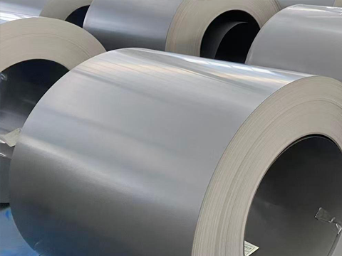
Grade Selection Dictates Compliance: Upgrading from legacy materials or lower-grade conventional CRGO (e.g., 27-M4) to thinner, high-permeability Hi-B grades (e.g., 23Q85, 27Q120) is often mandatory to meet Tier 2/DOE standards without increasing the physical footprint of the transformer.
The Industry Workhorse: CRGO remains the undisputed material of choice for power and distribution transformer core laminations due to its optimal balance of mechanical strength, saturation induction, and cost-effectiveness.
Hi-B vs. Conventional Trade-offs: High-permeability (Hi-B) CRGO offers superior magnetic flux density and lower core loss but requires precise handling and higher upfront material costs.
Manufacturing Realities Impact Performance: Theoretical core loss values are heavily influenced by the "building factor"; improper cutting, stacking (e.g., lack of step-lap joints), and inadequate stress-relief annealing can negate the benefits of premium CRGO grades.
Amorphous Core Competition: While amorphous metal provides the lowest no-load losses, CRGO remains the industry standard due to superior mechanical stability, higher saturation induction, and compatibility with existing manufacturing infrastructure.
Table of Contents
Establishing baseline metrics is essential when evaluating core materials for distribution transformers. The physical assembly of thin CRGO laminations directly impacts the effective magnetic cross-section. Factors like insulative coating thickness, surface flatness, and burr height limit eddy current circulation. A higher stacking factor ensures maximum magnetic material within a given core volume. When laminations are stacked, the microscopic gaps between layers reduce the overall density of the core. Engineers must account for this by applying a stacking factor, typically between 0.95 and 0.97 for high-quality silicon steel.
Magnetic permeability and saturation induction dictate how efficiently the material conducts magnetic flux. Transformer designs typically target 1.5T to 1.7T operating flux density. High saturation limits allow engineers to minimize the required core cross-section and reduce total transformer weight. Specific core loss, measured in watts per kilogram (W/kg), combines hysteresis and eddy current losses at standard frequencies and inductions. Evaluating these losses helps determine the long-term operational efficiency of the unit. Hysteresis loss occurs due to the continuous reversal of the magnetic field, which causes friction at the atomic level. Eddy current loss happens when the alternating magnetic field induces localized electrical currents within the steel itself.
To accurately measure these losses, manufacturers rely on standardized testing methods like the Epstein frame. This apparatus tests rectangular strips of the material under controlled conditions, providing a baseline W/kg value. However, the Epstein frame values represent ideal conditions. Real-world manufacturing introduces mechanical stresses that degrade these theoretical numbers. Engineers must apply a building factor to estimate the actual performance of the assembled core.
The insulative coating applied to the steel surface plays a massive role in performance. This coating, often a magnesium silicate or phosphate-based layer, provides electrical resistance between laminations. If the coating is too thin, eddy currents will jump between layers, causing localized heating and increased losses. If the coating is too thick, it reduces the stacking factor, meaning less active magnetic material fits into the core window. Finding the exact balance is a daily challenge on the production floor.
Deciphering the standard labeling conventions used by global mills is necessary to identify material properties accurately. Historical designations use AISI "M" grades, such as M3, M4, M5, and M6. These labels indicate core loss levels. Lower numbers generally represent lower losses and thinner materials. For example, 27-M4 represents a 0.27mm nominal thickness with specific magnetic characteristics suited for standard applications. These older standards are still widely used in regions where efficiency regulations are less stringent.
Modern high-permeability grade codes provide more granular data. Codes like 23Q85, 23Q90, and 27Q120 follow a specific structure. The first two digits represent the nominal thickness in hundredths of a millimeter. A prefix of "23" indicates a 0.23mm thickness. The letter "Q" designates the manufacturer's specific high-permeability or domain-refined process. The final digits represent the guaranteed maximum core loss at 1.7T at 50Hz. A designation of "85" indicates a maximum loss of 0.85 W/kg.
Understanding these codes allows procurement teams to substitute materials from different mills when supply chain issues arise. If a specific Japanese mill cannot deliver 23Q90, an engineer can look for an equivalent European or Chinese grade that meets the 0.23mm thickness and 0.90 W/kg loss limit. However, substituting grades requires careful verification of the material's mechanical properties, specifically its hardness and brittleness, as these affect the slitting and shearing processes on the factory floor.
The chemical composition of the steel also varies slightly between manufacturers, even within the same grade designation. Some mills use higher silicon content to increase electrical resistance, which lowers eddy currents but makes the steel more brittle. Others rely on precise temperature control during the rolling process to achieve the desired grain orientation. These subtle differences mean that a 23Q85 from one supplier might behave differently in the slitting machine than a 23Q85 from another, requiring operators to adjust blade clearances and tension settings.

Breaking down the primary tiers of available materials helps match the right steel to your specific transformer design requirements. Conventional grades, such as 27-M4, 30-M5, and 35-M6, feature standard grain orientation. They typically range from 0.27mm to 0.35mm in thickness. Transitioning from older hot-rolled silicon steel to a conventional grade like 27-M4 can reduce transformer core losses by up to 38 percent. These grades are the best fit for applications with lower kVA ratings or regions with less stringent efficiency mandates.
High-Permeability (Hi-B) grades, including 23Q85, 23Q90, and 27Q120, offer enhanced grain alignment. They utilize specialized silicon-iron alloys and precise chemical compositions, often incorporating aluminum nitride inhibitors. These materials are rolled to thinner gauges, typically 0.23mm to 0.27mm. They are the ideal choice for high-efficiency distribution transformers requiring reduced core loss and higher operating permeability without increasing physical core volume.
Laser-domain refined materials represent the highest efficiency tier within the silicon steel family. Surface treatments, such as laser etching or mechanical scribing, artificially refine magnetic domain spacing. This process drastically reduces eddy current losses. However, these materials cannot undergo stress-relief annealing at high temperatures, as the heat destroys the laser-induced domain refinements. Proper handling during core assembly is critical to maintaining their superior magnetic properties.
Material Category | Typical Thickness | Key Characteristics | Best Application |
|---|---|---|---|
Conventional (e.g., 27-M4) | 0.27mm - 0.35mm | Standard grain orientation, moderate core loss. | Standard efficiency requirements. |
Hi-B (e.g., 23Q85) | 0.23mm - 0.27mm | Enhanced alignment, lower losses, higher permeability. | Strict efficiency mandates, compact designs. |
Laser-Domain Refined | 0.23mm - 0.27mm | Surface etched for minimum eddy currents. | Ultra-high efficiency, non-annealed cores. |
When selecting between these grades, engineers must consider the manufacturing equipment available. Thinner Hi-B grades require sharper shear blades and tighter tolerances to prevent burr formation. A burr is a microscopic raised edge created during cutting. If the burr is taller than the insulative coating, it will bridge the gap between laminations, creating a short circuit for eddy currents and skyrocketing the core loss. Upgrading to a premium grade is useless if the factory's cutting equipment cannot handle the thinner material cleanly.

Comparing the industry workhorse against its primary alternative requires evaluating several technical dimensions. Amorphous metal yields significantly lower no-load losses, often up to 70 percent less than standard silicon steel. This makes amorphous cores highly attractive for utilities operating with low load factors where continuous no-load losses dominate the energy profile.
However, CRGO maintains a distinct advantage in saturation flux density. It operates at approximately 2.03T saturation compared to 1.56T for amorphous metal. This higher saturation limit allows transformers to be designed with a more compact footprint and lighter overall weight for the same kVA rating. Space-constrained urban installations heavily favor this compact design capability.
Saturation Limits: Silicon steel allows for smaller core windows and less copper winding, reducing the overall footprint.
Mechanical Stability: Amorphous metal is highly brittle and prone to shattering during assembly, requiring specialized handling.
Tooling Compatibility: Traditional steel works seamlessly with existing slitting and shearing lines.
Joint Design: Silicon steel supports complex step-lap joints, whereas amorphous is largely restricted to wound cores.
Manufacturing scalability also differs vastly. Silicon steel is highly machinable. It is easily sheared into complex laminations, supports traditional stacked core and step-lap joint designs, and utilizes existing factory tooling. Amorphous metal is extremely thin, typically around 0.025mm, and highly brittle. It requires specialized cutting and handling equipment to prevent metal flakes from causing short circuits. Consequently, amorphous materials are typically limited to wound core designs.
Acoustic noise is another critical factor. Silicon steel exhibits significantly lower magnetostriction at operating flux densities. Magnetostriction is the physical expansion and contraction of the core material as the magnetic field alternates. This movement generates the characteristic humming sound of a transformer. Because amorphous metal has higher magnetostriction, it produces more noise. Utilities require fewer noise-mitigation steps in residential or urban environments when deploying traditional cores compared to amorphous alternatives.
Actual transformer core losses often exceed the supplier's theoretical material data sheet values. Identifying and mitigating these implementation risks ensures the final product meets regulatory requirements. Mechanical stress from slitting, shearing, and stacking degrades the magnetic domain structure. This degradation causes a building factor—the ratio of actual core loss to raw material loss—greater than 1.0.
Implementing step-lap core construction and using precision-controlled shear blades optimizes flux distribution at the joints. These practices reduce localized saturation and minimize burr height, keeping the building factor as close to 1.0 as possible. Unrelieved mechanical stresses introduced during core winding or punching increase hysteresis loss. Establishing strict temperature-controlled, inert-atmosphere annealing processes for wound cores or punched laminations restores magnetic properties. Remember to exclude laser-treated grades from high-temperature annealing.
Supply chain constraints pose another risk. Global shortages of premium 0.23mm Hi-B materials occur due to competing demand from the electric vehicle sector for non-grain oriented steel production. Qualify multiple mills and standardize on flexible core geometries. Designs that accommodate slight variations in grade specifications, such as alternating between 23Q90 and 27Q120 based on availability, prevent production bottlenecks.
Handling the material on the factory floor requires strict protocols. Dropping a coil or allowing it to rest on an uneven surface induces stress that permanently damages the magnetic properties. Workers must use specialized lifting C-hooks and store coils in climate-controlled environments to prevent rust. Even the tension applied by the uncoiler during the slitting process must be carefully calibrated. Too much tension stretches the steel, altering its grain structure and increasing losses before the material is even cut.
Selecting the right CRGO grade requires balancing core loss, magnetic permeability, material thickness, mechanical stability, manufacturing capability, and long-term supply reliability. Engineers should evaluate both laboratory performance data and the additional losses introduced during cutting, stacking, handling, and transformer core assembly.
With more than 20 years of experience in the electrical steel market and over 16 years of manufacturing expertise, SHERAXIN supplies CRGO and CRNGO coils, strips, and sheets for transformer cores, EI laminations, and other electrical applications. Supported by customized production capabilities, material testing resources, and an established global supply network, SHERAXIN helps transformer manufacturers match magnetic performance, dimensions, processing requirements, and project budgets more effectively.
Audit your current core-cutting machinery to ensure compatibility with thinner, high-permeability grades.
Request guaranteed maximum core loss curves from your suppliers to verify material performance before bulk procurement.
Implement step-lap joint designs in your manufacturing process to minimize the building factor and reduce localized flux saturation.
Establish strict handling protocols on the factory floor to prevent mechanical stress and surface damage to the laminations.
A: Conventional grades have standard grain orientation and moderate core losses, typically ranging from 0.27mm to 0.35mm thick. Hi-B grades feature enhanced grain alignment, specialized alloys, and thinner gauges (0.23mm to 0.27mm), resulting in higher magnetic permeability and significantly lower core losses.
A: In modern codes like 23Q85, "23" denotes 0.23mm thickness, "Q" indicates high-permeability, and "85" means a maximum core loss of 0.85 W/kg at 1.7T. Older codes like 27-M4 indicate 0.27mm thickness with "M4" representing a standard historical loss tier.
A: Thinner laminations restrict the path of eddy currents, reducing the heat generated by magnetic flux. Upgrading from 0.30mm to 0.23mm steel significantly lowers eddy current losses, improving the overall efficiency of the transformer core.
A: Common conventional grades include 27-M4 and 30-M5 for standard applications. For high-efficiency transformers meeting strict regulatory standards, manufacturers frequently use Hi-B grades like 23Q85, 23Q90, and 27Q120.
A: Amorphous metal lacks a crystalline structure, reducing no-load losses by up to 70 percent. However, it has a lower saturation flux density, requires a larger physical footprint, is highly brittle, and necessitates specialized manufacturing equipment.
A: The building factor is the ratio of the actual measured core loss of the fully assembled transformer to the theoretical core loss of the raw material. It accounts for losses introduced by mechanical stress, cutting, and stacking during manufacturing.


